When it comes to designing electronic circuits, there is a wide variety of software programs available to assist engineers and hobbyists alike. These circuit design software suites cover the entire process, from initial schematic capture to printed circuit board (PCB) layout and fabrication. The top electronics CAD (computer-aided design) software programs include Autodesk EAGLE, Altium Designer, and Proteus, each offering a comprehensive set of tools for circuit design, simulation, and production.
Circuit design software plays a crucial role in the development of high-performing electronic devices, integrated circuits, and printed circuit boards. These tools enable designers to capture schematics, create PCB layouts, simulate circuit behavior, and ensure compliance with design rules and electromagnetic compatibility (EMC) standards. Whether you’re working on analog, digital, or mixed-signal circuits, the right circuit design software can streamline the design process and help identify issues early on, reducing overall project costs and time-to-market.
Key Takeaways
- Circuit design software enables engineers and hobbyists to create, simulate, and produce electronic circuits and printed circuit boards.
- Popular circuit design software programs include Autodesk EAGLE, Altium Designer, and Proteus, each with a comprehensive set of tools for the design process.
- These software suites cover the entire circuit design workflow, from schematic capture to PCB layout and fabrication, helping to ensure the development of high-performing electronic devices and components.
- Circuit design software offers features such as component libraries, PCB layout and routing, design rule checking, and simulation capabilities to streamline the design process and identify potential issues early on.
- Both free, open-source and commercial circuit design software options are available, catering to a range of user needs and budgets.
Circuit Design Process
The circuit design process is a multifaceted journey that involves several essential steps to create high-performing electronic circuits. According to the second source, this process generally involves the following key phases:
Defining the Purpose of the Circuit
The first step in the circuit design process is to clearly define the purpose and requirements of the electronic circuit. This crucial stage sets the foundation for the entire design, ensuring that the final product meets the desired functionalities and specifications.
Designing the Schematic
With the circuit’s purpose established, the next step is to design the schematic. This involves creating a visual representation of the electronic components and their interconnections, known as the schematic circuit diagram. The schematic design lays the groundwork for the subsequent stages of the circuit design process.
Simulating the Circuit
Before moving forward with the physical implementation, it is essential to simulate the circuit. This step allows designers to test the circuit’s behavior and identify any potential issues or errors within the design. Circuit simulation software plays a vital role in this phase of the circuit design process.
Creating the PCB Layout
Once the circuit simulation is successful, the PCB layout can be designed. This involves arranging the electronic components and routing the interconnections on a printed circuit board (PCB). The PCB layout is a critical step that ensures the circuit’s physical implementation aligns with the schematic design.
Fabricating the PCB
With the PCB layout complete, the next step is to fabricate the PCB. This process involves creating the physical circuit board, which can then be populated with the necessary electronic components.
Assembling and Testing
The final stage of the circuit design process is to assemble and test the circuit. This involves physically connecting the electronic components to the PCB and verifying that the circuit functions as intended. Any necessary adjustments or modifications can be made at this stage to ensure the circuit’s optimal performance.
The circuit design process is an iterative and collaborative endeavor, often involving multiple cycles of design, simulation, and testing to achieve the desired results. By following this comprehensive approach, electronic circuit designers can create innovative and reliable products that meet the evolving needs of the industry.
Popular Circuit Design Software

When it comes to circuit design, there are several software programs that stand out as industry leaders. These tools streamline the process of creating electronic circuits, from the initial schematic design to the final printed circuit board (PCB) layout. Let’s explore three of the most popular circuit design software options:
Autodesk EAGLE
Autodesk EAGLE is a widely used circuit design software program that offers a comprehensive suite of tools for electronic circuit design, PCB layout, and schematic capture. Known for its user-friendly interface and extensive component libraries, EAGLE enables circuit designers to quickly bring their ideas to life. With its intuitive design environment and advanced features, EAGLE is a popular choice for both hobbyists and professional electronics circuit design teams.
Altium Designer
Altium Designer is a powerful PCB design software that caters to the needs of professional circuit designers and electronic design automation (EDA) teams. This software provides a robust set of tools for schematic capture, PCB layout and routing, and design rule checking. Altium Designer’s advanced features, such as seamless collaboration, 3D visualization, and integrated simulation, make it a popular choice for complex electronic circuit design projects.
Proteus
Proteus is a comprehensive circuit design and simulation software suite that combines schematic capture, PCB layout, and circuit simulation capabilities. Known for its user-friendly interface and powerful simulation engine, Proteus is a popular choice among hobbyists, students, and small-scale electronics circuit design teams. Its extensive component library, intuitive design tools, and versatile simulation features make it an attractive option for those looking to design, test, and verify their electronic circuits before fabrication.
Autodesk EAGLE , Altium Designer , and Proteus , represent some of the most widely used circuit design software and PCB design software in the electronics industry. Each offers unique features and capabilities, catering to the diverse needs of circuit designers , electronic design automation teams, and electronics enthusiasts alike.
Open-Source Circuit Design Software

In the world of electronic circuit design, open-source software has emerged as a game-changer, empowering open-source designers, makers, hobbyists, students, and professionals with free, easy-to-use tools for their circuit design, PCB design, and electronic design automation (EDA) needs. These open-source solutions not only provide a cost-effective alternative to commercial software but also foster a collaborative community of open-source hardware enthusiasts dedicated to driving innovation and accessibility in the field.
KiCad
KiCad is a popular open-source software suite for schematic capture, PCB layout, and electronic design automation. Developed under the GNU Public License, KiCad offers a comprehensive set of features, including support for multi-layer PCBs, advanced routing capabilities, and a growing library of component models. Its intuitive interface and powerful design tools have made it a favorite among circuit designers, hobbyists, and students looking for a free and easy-to-use solution for their PCB design and circuit design needs.
CircuitMaker
CircuitMaker is another open-source circuit design software that has gained significant traction in the electronics community. Developed by Altium, CircuitMaker offers a feature-rich environment for schematic capture, PCB layout, and simulation, all without requiring a commercial license. Its intuitive user interface and integration with open-source EDA tools make it an attractive choice for designers, makers, and hobbyists seeking a powerful yet free and easy-to-use solution for their circuit design and PCB design projects.
Open Circuit Design
Open Circuit Design is a collaborative platform that provides a wide range of open-source circuit design resources, including schematics, PCB layouts, and design files. This platform empowers designers, makers, and hobbyists to design electronic circuits, printed circuit boards, and complex systems using a growing library of open-source hardware designs. By fostering a design reuse ecosystem, Open Circuit Design helps to accelerate the development of innovative electronic products and reduce the barriers to entry for aspiring open-source designers.
Circuit Simulation Software
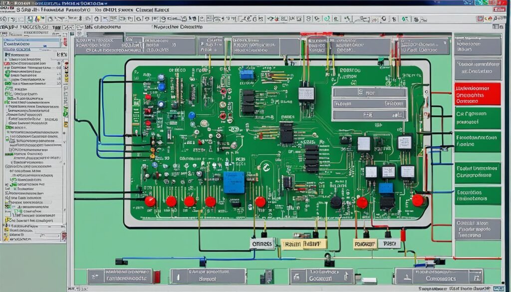
When it comes to designing and testing electronic circuits, circuit simulation software plays a crucial role. These tools allow engineers and hobbyists to model, analyze, and validate their circuit designs before moving to physical implementation. Several open-source and free circuit simulation software options are available, each offering unique features and capabilities to suit different needs.
ADS
ADS, or Advanced Design System, is a comprehensive circuit simulation software suite developed by Keysight Technologies. It is widely used in the design and analysis of analog, digital, and RF circuits, including integrated circuits (ICs) and printed circuit boards (PCBs). ADS provides advanced simulation capabilities, such as electromagnetic and thermal analysis, to help engineers identify and mitigate potential issues in their circuit designs.
OpenSCE
OpenSCE, or Open-Source Circuit Emulator, is a free and open-source circuit simulation software that offers a user-friendly interface and a wide range of simulation tools. It supports both analog and digital circuit simulation, allowing users to model and analyze the behavior of complex electronic circuits. OpenSCE is particularly useful for hobbyists, students, and small-scale projects due to its affordability and ease of use.
QSapecNG
QSapecNG is another open-source circuit simulation software that focuses on providing a simple and intuitive user experience. It is designed to be a lightweight and easy-to-use tool for simulating analog and digital circuits, including those involving semiconductor devices such as transistors and diodes. QSapecNG is often used by beginners and students in the field of electronic circuit design.
SimulIDE
SimulIDE is a free, open-source, and cross-platform circuit simulation software that combines schematic capture, simulation, and PCB layout in a single integrated environment. It supports a wide range of electronic components and allows users to design, simulate, and test their circuits before moving to physical implementation. SimulIDE is particularly useful for hobbyists, makers, and educational purposes due to its user-friendly interface and comprehensive feature set.
While these circuit simulation software options offer a range of capabilities, it’s important to note that they, like any simulation tool, have limitations. The accuracy of the simulation results can be affected by factors such as the complexity of the circuit, the accuracy of the component models, and the underlying assumptions of the simulation algorithms. Therefore, it is essential to carefully validate the simulation results and perform physical testing to ensure the reliability and functionality of the final circuit design.
Circuit Design

The circuit design process is a crucial step in the development of electronic devices and systems. It involves the conceptualization, planning, and implementation of electronic circuits to achieve specific functionalities. This multifaceted process encompasses various stages, from defining the circuit’s purpose to fabricating the physical printed circuit board (PCB).
At the core of circuit design lies the schematic capture, where designers meticulously map out the interconnections between electronic components, such as resistors, capacitors, and integrated circuits. This schematic serves as the blueprint for the subsequent stages, ensuring the circuit’s intended behavior is accurately represented.
Simulation and analysis tools play a vital role in the circuit design workflow, allowing designers to test the circuit’s performance and identify potential issues before the physical implementation. These software programs, often referred to as circuit simulation software, enable designers to explore the circuit’s behavior under various conditions, optimizing its design and ensuring its reliability.
The PCB layout stage transforms the schematic into a physical representation, strategically arranging the electronic components and their interconnections on a printed circuit board. This process requires careful consideration of factors such as signal integrity, power distribution, and electromagnetic compatibility (EMC) to ensure the circuit’s functionality and reliability.
Throughout the circuit design process, designers must adhere to industry-standard design rules and guidelines to ensure the circuit’s compliance with regulatory requirements and manufacturing constraints. This attention to detail is crucial for producing high-performing electronic devices that meet the evolving needs of the market.
PCB Design Tools
Designing printed circuit boards (PCBs) is an integral part of the electronics design process. Fortunately, there are a variety of powerful PCB design tools available to assist engineers and designers in creating high-performing electronic products. Some of the popular PCB design tools include:
Cadence OrCAD PCB Designer
Cadence OrCAD PCB Designer is a comprehensive suite of PCB design tools that enables schematic capture, PCB layout, and routing. It offers advanced features for signal integrity, power integrity, and electromagnetic compatibility (EMC) analysis, making it a popular choice for complex pcb design projects.
DesignSpark
DesignSpark is a free and easy-to-use pcb design software that provides a user-friendly interface for creating printed circuit boards. It includes tools for schematic capture, PCB layout, and design rule checking, making it an excellent choice for hobbyists, students, and small-scale designers.
Protel
Protel, now known as Altium Designer, is a powerful electronic design automation (EDA) suite that encompasses schematic capture, pcb layout and routing, and design rule checking. It is widely used in the industry for the design of complex printed circuit boards.
Cadstar
Cadstar is another comprehensive pcb design software that offers tools for schematic capture, pcb layout, and design rule checking. It is particularly well-suited for the design of high-speed and high-density printed circuit boards.
Sprint-Layout
Sprint-Layout is a user-friendly and affordable pcb design software that provides a streamlined interface for creating printed circuit boards. It is a popular choice for hobbyists, small businesses, and educational institutions due to its ease of use and affordability.
PADS PCB
PADS PCB is a comprehensive pcb design software that offers tools for schematic capture, pcb layout and routing, and design rule checking. It is known for its advanced features in signal integrity, power integrity, and electromagnetic compatibility analysis.
Circuit Design Software Features

When it comes to circuit design software, there are several key features that professionals and hobbyists alike often seek. These capabilities can greatly enhance the overall design process, from initial concept to final PCB fabrication. Let’s explore some of the essential features found in leading circuit design software suites.
Schematic Capture
One of the foundational features of circuit design software is schematic capture. This allows users to visually represent their electronic circuit designs, creating a clear and organized schematic diagram. Schematic capture tools often include comprehensive component libraries, enabling designers to easily select and place the necessary electronic components onto the virtual circuit board.
Component Libraries
Robust component libraries are crucial for circuit design software. These libraries contain a vast array of electronic components, including resistors, capacitors, integrated circuits, and more. The ability to quickly access and integrate these components into the circuit design streamlines the overall workflow, saving time and reducing the potential for errors.
PCB Layout and Routing
Once the schematic design is complete, circuit design software typically offers advanced PCB layout and routing capabilities. This allows designers to translate their schematic into a physical printed circuit board (PCB) layout, complete with precise component placement and interconnecting traces. Automated routing tools can help optimize the PCB layout, ensuring efficient signal paths and minimizing potential issues like signal integrity, power integrity, and electromagnetic compatibility.
Design Rule Checking
Circuit design software often includes built-in design rule checking (DRC) features. DRC examines the circuit design and layout, identifying any violations or issues that may arise, such as trace widths, clearances, and other critical design parameters. This helps catch potential problems early in the design process, enabling designers to make necessary adjustments before moving to the fabrication stage.
Simulation and Analysis
Many circuit design software suites offer integrated simulation and analysis tools. These features allow designers to virtually test and analyze their circuit designs, identifying potential issues or optimizing performance before committing to physical prototyping. Simulation capabilities may include analog, digital, and mixed-signal circuit analysis, as well as support for SPICE-based simulations and other advanced techniques.
By leveraging these key features, circuit design software empowers engineers, hobbyists, and professionals to create innovative and high-performing electronic circuits, from simple to complex designs. The combination of schematic capture, component libraries, PCB layout, design rule checking, and simulation capabilities streamlines the entire circuit design process, ultimately leading to more efficient and successful electronic product development.
Free vs. Paid Circuit Design Software
When it comes to and , both free and paid offer a range of features and capabilities. Free programs like , , and provide a cost-effective solution for hobbyists, students, and small-scale projects. These open-source tools often include essential features such as , , and basic .
On the other hand, like , , and offer more comprehensive and capabilities, often with advanced simulation, analysis, and features. These paid suites are typically geared towards professional , engineers, and companies working on complex and .
| Feature | Free Circuit Design Software | Paid Circuit Design Software |
|---|---|---|
| Cost | Free or low-cost | Subscription-based or perpetual licenses |
| Complexity | Simpler, easier to use | More advanced, feature-rich |
| Simulation and Analysis | Basic simulation capabilities | Comprehensive simulation, analysis, and optimization tools |
| Design Automation | Limited design automation features | Robust design automation and optimization tools |
| Support and Documentation | Community-driven support and documentation | Vendor-provided support, training, and comprehensive documentation |
| Project Complexity | Suitable for smaller, less complex | Capable of handling complex , , , and |
The choice between free and paid ultimately depends on the complexity of the being designed, the required features, and the available budget. Free options may be a good fit for hobbyists, students, and small-scale projects, while paid solutions are often necessary for professional-grade and tasks, especially those involving advanced , , and considerations.
Choosing the Right Circuit Design Software
When selecting the appropriate circuit design software, there are several crucial factors to consider. The choice between open-source and commercial software, as well as entry-level and professional-grade tools, can significantly impact the design process and the final product.
Open-Source vs. Commercial
Open-source circuit design software, such as KiCad and CircuitMaker, offers a cost-effective solution for hobbyists, students, and small businesses. These tools are often free, highly customizable, and supported by a vibrant community. In contrast, commercial software like Autodesk EAGLE and Altium Designer typically provide more advanced features, comprehensive libraries, and robust technical support, but at a higher price point. Circuit designers must weigh the benefits of open-source flexibility against the capabilities of commercial software to determine the best fit for their project needs and budget.
Entry-Level vs. Professional
Entry-level circuit design software, often free or low-cost, is an excellent choice for beginners, hobbyists, and those working on simple projects. These tools generally have a user-friendly interface and streamlined functionality, making them accessible for users with limited experience. Professional-grade software, on the other hand, caters to experienced circuit designers working on complex, high-performance electronic designs. These programs offer advanced features, such as integrated circuit (IC) design, signal integrity analysis, and electromagnetic compatibility (EMC) simulation, which can be essential for designing cutting-edge electronics.
Also Read : How Do You Design A Circuit For A Specific Application?
Compatibility and Integration
Ensuring seamless compatibility and integration between the circuit design software and other tools in the electronic design automation (EDA) ecosystem is crucial. Circuit designers should consider factors like file format compatibility, data exchange capabilities, and the ability to integrate with simulation, layout, and manufacturing tools. This level of integration can streamline the design process, reduce errors, and facilitate a more efficient workflow, ultimately leading to the successful development of high-quality electronic circuits.
FAQs
Q: What software is commonly used for electronic circuit design?
A: Some popular software used for electronic circuit design include Altium Designer, OrCAD, Eagle, KiCad, and LTspice.
Q: How does electronic design automation software help in circuit design?
A: Electronic design automation (EDA) software helps automate the design process, making it more efficient and accurate for circuit designers.
Q: What are some basics of circuit design that every designer should know?
A: Some basic concepts of circuit design include understanding Ohm’s Law, resistor values, capacitor and inductor behavior, and basic circuit analysis techniques.
Q: What is the role of a circuit simulator in the electronic circuit design process?
A: A circuit simulator allows designers to test and verify the functionality of their circuit designs in a virtual environment before implementing them in hardware.
Q: Can you recommend any free PCB design software for beginners?
A: Some popular free PCB design software for beginners include KiCad, EasyEDA, and Fritzing.
Q: What is the design cycle for creating complex electronic circuits?
A: The design cycle for complex electronic circuits typically involves multiple steps such as concept development, schematic design, circuit simulation, PCB layout, prototyping, and testing.
Q: How do designers ensure proper functionality and reliability in circuit designs?
A: Designers ensure proper functionality and reliability in circuit designs by conducting thorough testing, simulations, and following best practices in electronic design.
Source Links
- https://www.proto-electronics.com/blog/our-top-10-printed-circuit-design-software-programmes
- https://www.electronicsforu.com/special/cool-stuff-misc/open-source-circuit-design-software
- https://www.autodesk.com/solutions/circuit-design-software


