Printed Circuit Boards (PCBs) are essential components in electronic devices, serving as the foundation for electrical circuits. However, PCBs can fail for various reasons, including physical damage, manufacturing defects, and environmental factors. Knowing how to repair PCBs is crucial, as it can save time and money compared to replacing the entire board. This article will explore the best techniques for repairing printed circuit boards, from troubleshooting and component replacement to soldering and quality control.
Key Takeaways
- Printed Circuit Boards (PCBs) are the backbone of electronic devices, but they can fail due to various reasons.
- Repairing PCBs can be more cost-effective than replacing the entire board.
- Visual inspection, troubleshooting, and component replacement are essential steps in PCB repair.
- Proper use of tools and materials, such as a multimeter, soldering iron, and copper tape, is crucial for effective PCB repair.
- Understanding PCB layers and materials can help guide the repair process and ensure the board’s functionality is restored.
Introduction
Repairing printed circuit boards (PCBs) is an essential skill in the world of electronics, as it can save you time and money compared to replacing the entire board. PCBs are integral components in a wide range of electronic devices, from smartphones to industrial equipment, so being able to troubleshoot and fix them is crucial. Understanding the importance of PCB repair and the common causes of PCB failures is the first step in mastering this valuable technique.
Importance of Repairing Printed Circuit Boards
PCBs are often found in critical applications, such as medical devices, transportation systems, and communication infrastructure. When a PCB fails, it can have serious consequences, ranging from inconvenience to safety hazards. By learning how to effectively repair PCBs, you can minimize downtime, reduce replacement costs, and ensure the continued reliability of your electronic devices. PCB repair is a valuable skill that can benefit both individuals and businesses.
Common Causes of PCB Failures
There are several common reasons why printed circuit boards may fail, including physical damage, manufacturing defects, component failures, environmental factors, and static electricity damage. Understanding these potential causes is essential for developing effective PCB troubleshooting and repair strategies. By identifying the root cause of the problem, you can select the appropriate repair techniques to restore the PCB to full functionality.
Physical damage, such as cracks, scratches, or burns, can occur due to accidents, mishandling, or extreme environmental conditions. Manufacturing defects, including poor solder joints, incorrect component placement, or design flaws, can also lead to PCB failures. Component failures, caused by wear and tear or electrical overloads, can disrupt the board’s operation. Environmental factors, like moisture, heat, or corrosion, can degrade the PCB’s materials and connections over time. Finally, static electricity can damage sensitive components and cause malfunctions.
By understanding these common PCB failure scenarios, you can develop a comprehensive approach to circuit board repair that addresses the root causes of the problem and restores the board to its full functionality.
Visual Inspection

The first step in repairing a printed circuit board is to perform a pcb visual inspection. This can help identify the source of the problem, such as loose connections, damaged components, or poor solder joints. By closely examining the PCB, you can uncover potential issues that may be causing the malfunction.
Checking for Loose Connections
Carefully inspect the PCB for any loose connections, which can result in intermittent or complete failure of the circuit. Look for components that are not securely seated in their sockets or connectors that are not properly mated. Gently wiggle the components and connections to check for any play or movement.
Identifying Damaged Components
Scan the PCB for signs of physical damaged components, such as burnt, discolored, or swollen parts. These visual cues can indicate component failure, which may require replacement. Pay close attention to capacitors, resistors, and integrated circuits, as they are common points of failure.
Inspecting Solder Joints
Thoroughly examine the solder joints on the PCB. Proper solder joints should be smooth, bright, and evenly flowed. Dull, uneven, or cracked solder joints can signal potential issues that need to be addressed. Additionally, check for any solder bridges between adjacent copper traces, which can cause short circuits.
By conducting a thorough pcb troubleshooting visual inspection, you can identify the root causes of the PCB’s problems and develop an effective repair plan. This step is crucial for ensuring the successful restoration of the board’s functionality.
Tools and Materials Needed

Before starting the repair process, it’s essential to gather all the necessary pcb repair tools and materials. The most important tools include a multimeter for testing voltages and continuity, a soldering iron and solder for making repairs, and tweezers and cutters for precise component handling and removal. Additionally, you may need cotton swabs, rubbing alcohol, a hot air gun, and adhesive copper tape for certain repairs. Having all these pcb repair materials on hand will help ensure a smooth and efficient repair process.
Multimeter
A multimeter is a crucial tool for troubleshooting and testing the electrical components on a printed circuit board. It can be used to measure voltage, current, and resistance, helping you identify any issues with the power supply or individual components.
Soldering Iron and Solder
A good quality soldering iron and the right type of solder are essential for making repairs to the PCB. The soldering iron will allow you to precisely heat and melt the solder to create new connections or replace damaged components.
Tweezers and Cutters
Delicate tweezers and precision cutters are necessary for handling small components and removing them from the PCB without causing any damage to the board or surrounding traces.
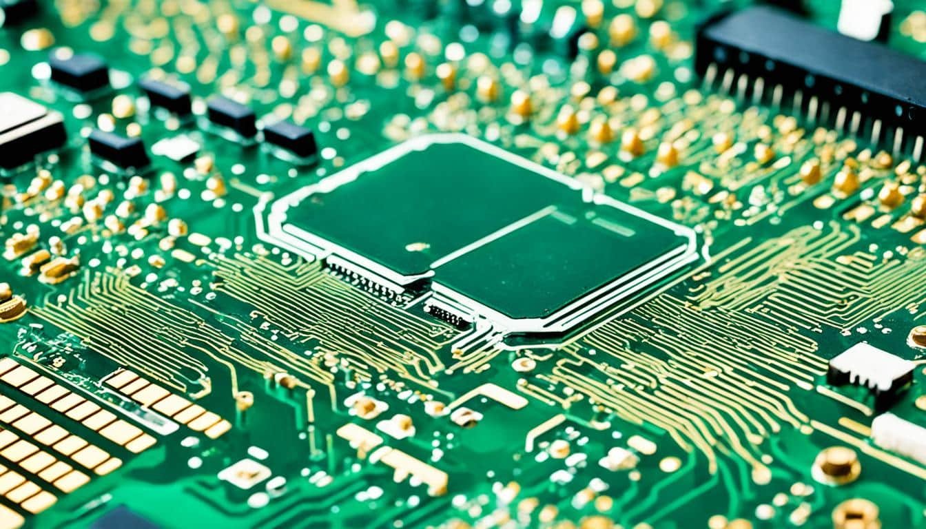
Printed Circuit Boards

Printed circuit boards (PCBs) are the backbone of modern electronics, providing a robust and reliable platform for electrical components and interconnections. To effectively repair a PCB, it is essential to understand the various layers and materials that comprise these essential devices.
Understanding PCB Layers
A typical PCB is constructed with multiple layers, each with a specific purpose. The core layers consist of copper traces that carry electrical signals and power, while the insulating layers, such as fiberglass or epoxy, provide separation and structural integrity. Protective coatings, such as solder masks and surface finishes, are also applied to shield the board and enhance its durability. Comprehending the relationship between these different layers is crucial for identifying and addressing issues during the repair process.
Types of PCB Materials
PCBs can be manufactured using a variety of materials, each with its own unique properties and applications. Fiberglass-reinforced epoxy (FR-4) is one of the most common and versatile PCB materials, offering a balance of strength, thermal stability, and cost-effectiveness. Other materials, such as polyimide (used in flexible pcbs), metal-core boards (for high-power applications), and high-density interconnect (HDI) boards, are also widely used in the industry. Knowing the specific materials used in the PCB you are repairing can help guide your repair strategy and ensure the board’s functionality is restored.
Understanding the complex layering and diverse materials used in PCBs is essential for effectively troubleshooting and repairing these critical electronic components. By familiarizing yourself with these fundamental concepts, you can develop a comprehensive approach to PCB repair and ensure the long-term reliability and performance of the devices you work on.
Troubleshooting Techniques

Once the visual inspection is complete, the next step in pcb troubleshooting is to utilize various techniques to identify the underlying cause of the PCB failure. This multi-faceted approach may involve checking the power supply voltages at numerous test points using a multimeter, as well as signal tracing with an oscilloscope to ensure the proper waveforms and logic levels are present throughout the circuit.
Comparing the behavior of the faulty board to a known good board can also serve as a useful pcb diagnosis strategy. By systematically testing and analyzing the PCB, technicians can pinpoint the specific problem area and develop an effective repair plan.
Checking Power Supply Voltages
Ensuring the correct power supply voltages are present on the PCB is a critical step in the troubleshooting process. Using a multimeter, technicians can measure the voltages at various test points to verify that each power rail is providing the expected levels of DC power to the connected components.
Signal Tracing with an Oscilloscope
In addition to checking power supply voltages, signal tracing with an oscilloscope can provide valuable insights into the PCB’s behavior. By observing the waveforms and logic levels at different test points, technicians can identify any anomalies or discrepancies that may be contributing to the board’s malfunction.
Component Replacement

If the troubleshooting process reveals a damaged or malfunctioning pcb component, the next step is to replace it. This involves carefully desoldering the old component and removing it from the PCB, then soldering a new replacement component in its place. Proper desoldering technique is crucial to avoid damaging the PCB’s traces or pads.
Desoldering and Removing Components
When desoldering and removing a component from the PCB, it’s important to use the right tools and techniques to avoid causing any further damage. This may involve using a desoldering pump or braid to carefully draw the solder away from the component’s leads, allowing you to gently lift it off the board.
Soldering New Components
Once the old component has been removed, it’s time to solder the new replacement component in its place. When soldering the new component, it’s important to ensure a strong, reliable connection by applying the correct amount of solder and ensuring the component is properly aligned on the PCB pads. This will help ensure the pcb assembly functions as intended.
Tracing and Repairing Broken Tracks

When a printed circuit board (PCB) experiences damage, one of the most common issues that can arise is broken copper traces. These traces, which carry electrical signals throughout the board, can become disrupted, causing the PCB to malfunction. To address this problem, you can utilize a technique known as pcb trace repair using adhesive copper tape.
Using Copper Tape for Track Repairs
The process of repairing a broken PCB trace with copper tape is relatively straightforward. First, you’ll need to carefully clean the area around the damaged trace, removing any debris or oxidation. Then, you can cut a small strip of the copper tape and apply it directly over the break, ensuring a secure and continuous connection. By bridging the gap with the conductive tape, you can restore the electrical continuity and get the PCB back in working order.
Restoring Through-Holes
In addition to repairing damaged copper traces, you may also need to address any through-hole repair on the PCB. Through-holes are the plated-through holes that connect the different layers of the board, and they can become compromised due to pcb damage or wear and tear over time. To restore these critical connections, you’ll need to carefully clean the affected through-holes and, if necessary, solder new components or wiring to re-establish the pcb track repair.
By leveraging techniques like copper tape application and through-hole restoration, you can effectively pcb trace repair and bring a malfunctioning PCB back to life. These methods allow you to target specific areas of damage, rather than having to replace the entire board, saving time and money in the process.
Testing and Quality Control
After completing the PCB repair, it’s essential to thoroughly test the board to ensure it is functioning properly. This comprehensive testing and quality control process will help verify the reliability and safety of the repaired printed circuit board.
Functional Testing
The first step in the testing phase is to power on the board and verify the correct voltages and signals at various test points. This ensures that the repaired components are properly integrated and the electrical connections are functioning as intended. Performing comprehensive functional testing, such as simulating real-world operating conditions, will validate the PCB’s overall performance and identify any remaining issues that need to be addressed.’
Also Read : Why Are PCBs Important?
Inspection and Quality Assurance
In addition to the functional testing, a thorough visual inspection of the repaired PCB should be conducted. This final quality assurance step allows for the identification of any missed problems, such as loose solder joints, damaged traces, or other potential issues that could impact the board’s reliability. By meticulously inspecting the PCB, you can have confidence that the repair work has been completed to the highest standards and the board will perform reliably in its intended application.
FAQs
Q: How can you repair a printed circuit board (PCB)?
A: Repairing a PCB typically involves identifying the faulty components, desoldering them, and then replacing with new components. It requires specialized tools and skills to diagnose and fix issues on a PCB.
Q: What are the common issues that may occur in PCBs?
A: Common issues in PCBs include faulty components, damaged traces, soldering defects, and short circuits. These issues can affect the functionality of the circuit board.
Q: How does the manufacturing process of PCBs work?
A: The manufacturing process of PCBs involves designing the circuit layout, etching the board, drilling holes for components, and soldering the components onto the board. It is a precise and intricate process that requires expertise.
Q: What is the importance of signal integrity in PCB design?
A: Signal integrity in PCB design refers to the quality of signals transmitted through the board without distortion or loss. It is crucial for maintaining the performance and reliability of electronic devices.
Q: What are the main materials used in circuit board design?
A: Circuit board materials include substrates, laminates, and copper layers. These materials form the foundation of PCBs and impact their performance and durability.
Q: What are multi-layer PCBs and how are they beneficial?
A: Multi-layer PCBs consist of several layers of substrate with copper traces between them. They offer more routing options, reduced electromagnetic interference, and compact design compared to single-layer PCBs.
Q: What is the difference between rigid and flexible PCBs?
A: Rigid PCBs are made of solid materials like fiberglass, while flexible PCBs use flexible materials like polyimide. Rigid PCBs are sturdy and suitable for most applications, while flexible PCBs are more versatile and can bend or fold.
Q: What are the components of a printed circuit board (PCB)?
A: A PCB consists of a layer of copper laminated onto a non-conductive substrate, with circuitry etched onto the copper layer to create an electronic circuit.
Q: How is a multi-layer PCB different from a rigid printed circuit board?
A: A multi-layer PCB has multiple layers of copper separated by insulating materials, whereas a rigid printed circuit board typically has a single layer of copper on a rigid substrate.
Q: What is the role of surface mount technology in PCB assembly?
A: Surface mount technology is a method used to mount electronic components directly onto the surface of a PCB, as opposed to through-hole mounting techniques.
Q: How are buried vias used in circuit board materials?
A: Buried vias are used to create connections between different layers of a PCB without being visible from the outside, allowing for more compact designs and better signal integrity.
Q: What are the different types of PCB assembly services available?
A: PCB assembly services include components sourcing, PCB fabrication, component placement, soldering, testing, and inspection to ensure the board meets quality standards.
Q: How do rigid-flex circuit boards combine the features of rigid and flexible boards?
A: Rigid-flex circuit boards combine sections of rigid PCBs with flexible circuitry, allowing for complex designs that require both the rigidity of a traditional PCB and the flexibility of a flexible circuit.
Q: What is the significance of high temperature materials in metal core printed circuit boards?
A: High temperature materials in metal core printed circuit boards are crucial for applications that require boards to withstand elevated temperatures, such as in automotive or industrial settings.
Source Links
- https://www.candorind.com/blog/how-to-fix-a-pcb-board/
- https://www.nutsvolts.com/magazine/article/repairing-circuit-boards
- https://jhdpcb.com/blog/pcb-repair-guide/